

Description
function of the SI
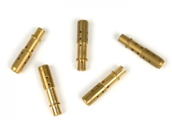
there is always a defined level of fuel in the SI carburettor nozzle area (depending on the volume in the float chamber). I.e. below the atomizer tube (which opens into the intake area of the carburetor) there is a fuel oil level. For this reason we also advise against the so-called float chamber spacers. These increase the level in the carburetor, but also provide a higher level in the nozzle area, which makes the premixing not work properly anymore and under certain circumstances gasoline may run (flood) from the atomizer directly into the engine. The real problem is not a too small volume of the float chamber but a tuning via the air nozzle. From the very bottom of the float chamber the amount of gasoline flowing into the engine is defined by the main nozzle. In the middle is half in the gasoline, half in the air, the so-called mixing tube (e.g. BE3). From the top, the air nozzle defines the amount of air flowing downstream.
MIXTING TUBE
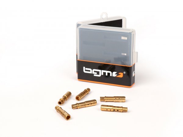
The feed process in the mixing tube is very complex and strongly dependent on pressure and speed. The mixing tube has various cross holes. These are partly in the gasoline level, partly outside of it in the air area. Depending on the size, quantity and positioning of the bore, a different advance rate behaviour results. It should be noted that there is generally no per se greasing or emaciating mixing tube.
BE4 - BE6 - BE5 - BE1 - BE3 - BE2
In this list, from left to right, the mixing tube is rather greasing at low rotational speed and emaciating at high rotational speed. The whole tilts accordingly and becomes lean at low speed and greasy at high speed. Attention: The mixing tubes have an effect over a very wide speed range. A BE4 mixing tube, for example, greases strongly just above the idle slide valve position. A BE2 on the other hand is relatively lean in the lower expansion range, but greases strongly from the top.
The most common used mixing tube BE3 covers 90% of all applications of the SI carburettor. In addition, the gas slide used should be checked here (see SI slide).
TIP
The combination of air nozzle 160 with mixing tube BE3 is sufficient in almost all cases. If the filter bottom is drilled and/or a resonance exhaust is installed, the mixing tube can be adjusted to BE2 and the air nozzle to 140.
(US)
em>AI-translation
+----------+
Manufacturer Information
Pinasco
Via Piemonte 5
31050 Morgano - Italy
https://www.pinasco.com/
info@pinasco.com
Responsible Person for the EU
Pinasco
Via Piemonte 5
31050 Morgano - Italy
https://www.pinasco.com/
info@pinasco.com
incl. VAT plus shipping costs
| Customers alternatively searched for | |
|---|---|
| Mischrohr | Zerstäuber | Atomiser | Vormischung | Düse | Jet | Jet Stack | Diffuseur | Polverizzatore | Mezclador | Tube D’Émulsion | Calibrator | Emulsionatore | Atomizador | |
Fits the following vehicles
- Vespa (Augsburg) Vespa 150 T/4 (type 332, 3-speed) (VGLA1T)
- Vespa (Augsburg) Vespa 150 T/4 (type 332, 4-speed) (VGLB1T)
- Vespa (Augsburg) Vespa 150 T/4 (type 202, VGLA1T)
- Vespa (Piaggio) P 80 X (V8X1T, -1983)
- Vespa (Piaggio) PX 80 E FL (V8X1T, 1983-)
- Vespa (Piaggio) PX 80 E FL Elestart (V8X1T, 1984-1990)
- Vespa (Piaggio) Vespa 150 (VBA1T)
- Vespa (Piaggio) Vespa 150 (VBB1T)
- Vespa (Piaggio) Vespa 150 (VBB2T)
- Vespa (Piaggio) Vespa 150 Super (VBC1T)
- Vespa (Piaggio) Vespa 150 GL (VLA1T)
- Vespa (Piaggio) Vespa 150 Sprint (VLB1T)
- Vespa (Piaggio) Vespa 150 Sprint Veloce (VLB1T)
- Vespa (Piaggio) Vespa 125 GTR (VNL2T)
- Vespa (Piaggio) Cosa 150 CL (VLR1T)
- Vespa (Piaggio) Cosa 150 CLX (VLR1T300)
- Vespa (Piaggio) Cosa 150 FL (VLR2T)
- Vespa (Piaggio) P 150 X (VLX1T, -1980)
- Vespa (Piaggio) PX 150 E FL (VLX1T, 1984-1997)
- Vespa (Piaggio) PX 150 E (VLX1T, 1981-1983)
- Vespa (Piaggio) Vespa 125 (VNA1T)
- Vespa (Piaggio) Vespa 125 (VNA2T)
- Vespa (Piaggio) Vespa 125 (VNB1T)
- Vespa (Piaggio) Vespa 125 (VNB3T)
- Vespa (Piaggio) Vespa 125 (VNB4T)
- Vespa (Piaggio) Vespa 125 (VNB5T)
- Vespa (Piaggio) Vespa 125 (VNB6T)
- Vespa (Piaggio) Vespa 125 Super (VNC1T)
- Vespa (Piaggio) Vespa 125 GT (VNL2T)
- Vespa (Piaggio) Vespa 125 TS (VNL3T)
- Vespa (Piaggio) Cosa 125 CL (VNR1T)
- Vespa (Piaggio) Cosa 125 CLX (VNR1T300)
- Vespa (Piaggio) Cosa 125 CLX (VNR1T301)
- Vespa (Piaggio) P 125 X (VNX1T, -1983)
- Vespa (Piaggio) PX 125 E FL (VNX2T, 1984-1997)
- Vespa (Piaggio) PX 125 T5 (VNX5T)
- Vespa (Piaggio) Vespa 180 Rally (VSD1T)
- Vespa (Piaggio) Vespa 200 Rally (VSE1T, Femsa)
- Vespa (Piaggio) Vespa 200 Rally (VSE1T, Ducati)
- Vespa (Piaggio) Cosa 200 CL (VSR1T)
- Vespa (Piaggio) Cosa 200 CLX (VSR1T300)
- Vespa (Piaggio) Cosa 200 FL (VSR1T301)
- Vespa (Piaggio) P 200 E (VSX1T, -1980)
- Vespa (Piaggio) PX 200 E FL (VSX1T, 1984-1997)
- Vespa (Piaggio) PX 200 E (VSX1T, 1981-1983)
- Vespa (Piaggio) PX 125 E FL (ZAPM09300, 1998-2000)
- Vespa (Piaggio) PX 125 E FL (ZAPM09302, 2001-)
- Vespa (Piaggio) PX 150 E FL (ZAPM09400, 1998-2000)
- Vespa (Piaggio) PX 150 E FL (ZAPM09401, 2001-)
- Vespa (Piaggio) PX 200 E FL (ZAPM18, 1998-)


